|
|
NET 211 - Wireless Networking
Chapter 6, Media Access Control Layer Standards
Objectives:
This lesson discusses functions on the Data Link layer,
Media Access Control sublayer. Objectives important to this lesson:
- Wireless LAN service sets
- MAC frames
- MAC layer functions
Concepts:
Chapter 6
As we noted in the last chapter, there are wireless functions
that take place on other layers than the Physical layer. The text tells
us that all WLAN features take place on the PHY (Physical) layer and
the MAC layer, which is actually part of the Data Link layer.
| Layer Number |
ISO Layer |
Functional Description |
| 7 |
Application |
services and programs |
| 6 |
Presentation |
translation across networks |
| 5 |
Session |
setting up and ending connections |
| 4 |
Transport |
guarantee delivery |
| 3 |
Network |
find other networks |
| 2 |
Data-Link |
media access control (MAC) and
logical link control (LLC)
|
| 1 |
Physical |
wiring, bit transmission, sending and
receiving network signals |
The text begins its discussion of Layer 2 by defining a service
set as all the devices that are associated with a wireless LAN.
This is not very enlightening, so let's see three examples of service
sets. Each of them has specific terms, definitions, and acronyms.
- Basic Service Set (BSS)
- One or more wireless devices,
called stations, that are served by one
access point. The AP
should be connected to a network, but the definition does not require
it. Each BSS is actually given two identifiers.
- The Service Set
Identifier (SSID) is the
ID that is assigned to this WLAN. It may or may not be broadcast. It is
typically an alphanumeric string assigned
by the administrator of the
LAN.
- The Basic Service Set
Identifier (BSSID) is
the MAC address of the AP. It
is not set by the administrator. It is hard
coded by the manufacturer
of the AP. Frames transmitted at Layer 2 use MAC addresses to identify
their source and destination.
- As if those acronyms were not confusing enough, the text
tells us about the Basic Service Area
(BSA) of a WLAN. The BSA is the
geographic area covered
by the AP's RF transmissions. In terms of relative size of a BSA:
- The BSA of an 802.11a WLAN is the smallest.
- The BSAs of 802.11b and 802.11g WLANs are about the
same size.
- The BSA of an 802.11n is the largest of the four types
mentioned in the text.
- Factors that diminish service on a WLAN: obstructions to
the signals, too many users, users consuming large parts of the
bandwidth, and distance from the AP.
- The text recommends that the number of users on a BSS
WLAN be limited to between 15 and 25. It warns us that users at the
outer range of the AP will have slower data rates due to dynamic rate switching.
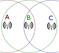
- Extended Service Set
(ESS) - This method addresses
the limit on the number of users by increasing the number of APs and
connecting their WLANs. An ESS
is defined as two or more BSS LANs
that connect to each other. This is the basis of a cell system, and it allows a station
to roam from one cell to
another.
The illustrations in the text agree with this
discussion on a site that sells practice equipment for Cisco
certifications. Their illustration shows the concept shown on page 202,
that the individual BSS WLANs should be linked into one common network.
- The text discusses a problem with roaming from one cell to another.
In the system shown on page 201, the cells are part of the same network,
which allows roaming from one cell to another, keeping the same IP
address for each station. This is Layer
2 roaming. All devices are in the same
network.
- The illustration on page 202 shows two switches that join
at one router. The system administrator has set up separate subnets on
each AP, which means they are different networks, which means that a
station roaming from one cell to the other will need a new IP address
in the new cell. This will cause the station to drop off the first
network, to have to join the second network, and to lose connection
with anything the user was doing on the network. This can work, but
users have to know it is going to happen or they will be very unhappy.
This is Layer 3 roaming.
Devices are in different
networks.
- A workaround for the problem of dropping off a network in
Layer 3 roaming is explained on page 202. The roaming station uses
Mobile IP, which assigns it a permanent IP address on its home network.
That address communicates with software called a foreign agent that acts like a proxy
server for each new foreign network.
In a sense, the IP stack has two addresses at any given time: the one
on the station's home network, and the one on the current foreign
network, and the foreign agent acts like a router between the two.
- Another key term is the Distribution
System (DS) that is the
system the BSS systems in an ESS use to communicate with each other. It
determines whether a frame in the system needs to be sent across a
wire, to another BSS, or to a station on a BSS. The text explains that
it is actually software on each AP.
- If the APs in an ESS system are connected by wireless
means, then they use a Wireless
Distribution System (WDS).
- Independent Basic Service
Set (IBSS) - This type
of system has no access
points. It is more like a peer-to-peer
network between some number of
stations. This is also called an ad-hoc
network. This kind of arrangement could take place between stations in
one of the other types, but it would not be needed in those cases. The
key thing about this system is that it only uses stations, and it does
not connect to another network. Other texts tell this story
differently, saying that this kind of service set can act as a bridge
between the other types. Our text does not mention this possibility.
The chapter continues with what it tells us will be a
discussion of frames, but it gives us more background on the internal processes of the ISO-OSI model
first. One bit of trivia is about the passing of data from one layer to
another.
- Data is passed from one
layer to the next in inbound and outbound traffic. The
discussion in the text is about an outbound
message/request.
- Each layer receives
data units from the layer above it.
- A Service Data Unit
(SDU) is a unit that has been
received, but not processed to pass to the next layer yet.
- A Protocol Data Unit
(PDU) is a unit that has been processed to pass down to the next
layer.
- Different things are done on each layer to process these
data units, but the layers have one thing in common. They each encapsulate the data units that they
receive. This means that they wrap their own kind of header and footer around whatever
they received from the upper
layer, in preparation of handing it to the next lower layer. It is as though mail was being passed down the network layers, and the mail room on each level puts each outgoing message in a new, bigger envelope before delivering it to the
mail room at the next lower
layer.
- In this way, a layer receives an SDU and prepares it to be a PDU that it will hand off to the
next layer. That PDU is viewed as an SDU
by the next receiving layer, where is it wrapped in a new header and footer.
It becomes that layer's PDU,
and it is handed down to the next layer.
- For incoming
messages, the process is reversed. Incoming
messages are unwrapped, processed, and handed up by each layer in turn.
This is illustrated in the figure on page 205. The book should have
made it clearer that the data is being sent by one device and is being
received by another.
The text tells us on the next page that 802.11n has a new feature. It can aggregate data units that are being
sent to the same device. This means that the service data units may be combined into one unit, providing
that they are being sent to the same other device, and providing they
are small enough to fit in one Aggregate
MAC SDU. These SDUs can be aggregated in turn, which makes them Aggregate MAC PDUs.
The text changes the subject just a bit on page 207, telling
us that there are differences between the frames used in 802.11 systems
and frames used in 802.3 (wired
Ethernet systems) that they must interact with. We are reminded
that most wireless systems operate in infrastructure
mode, which means that they connect to a wired system.
To understand a problem that occurs in many systems, you need
to know that frames are limited to different sizes in different kinds
of networks. The measure of size the book recommends is the MTU: the Maximum Transmission Unit. This is a
measure of the entire frame, including the header, footer, and data
portions.
- the MTU for a standard 802.3 Ethernet frame is 1500 bytes
- the MTU for an 802.11 frame is 2304 bytes
- the MTU for an aggregate MAC DSU (A-MDSU) is 7935 bytes
- the MTU for an aggregate MAC PDU (A-MPDU) is 64 kilobytes
So, how do we handle that kind of mess? The text describes
three ways such inconsistencies are made to operate together:
- fragmentation -
Frames can be broken into pieces that will fit the rules of the network
being used. Each piece can be wrapped in the appropriate frame
material. They are numbered for reassembly by the receiver.
- jumbo frames - All
devices on the network can be set to allow frames that range from 1500
bytes to 9000 bytes. These are jumbo frames. Note that they are still
smaller than the aggregate PDUs.
- lowest common denominator
- In this strategy, wireless devices are configured to limit their
frame sizes to 1500 bytes. The text tells us this is often a default
setting for wireless devices.
Moving to the bottom of page 208, we are reminded, painfully,
that a Layer 2 frame will be received by Layer 1 and will be wrapped in
an appropriate frame at that layer.
The text discusses three types of MAC frames: management
frames, control frames, and data frames.
- Management frames -
These are used to set up and maintain connection between stations and
APs, and between stations in an IBSS. There are several types of
management frames, and each has a different purpose regarding sessions.
I have reordered the list below. I hope it makes more sense.
- beacon frame
- a broadcast announcement that an AP is running and available;
contains the AP's SSID and connection parameters; contents of a beacon
frame:
- beacon interval - the time between successive beacon
transmissions; typically 100 ms
- timestamp - essentially an official network time for
any device joining the AP's LAN
- SSID - the ID of the AP's LAN
- supported rates - transmission rates that the AP can
support
- parameter sets - protocols that can be used on the the
WLAN and the settings used for them
- capability information - required characteristics for
workstations to be able to connect to this WLAN
- association request frame
- sent by a device, a request to join the APs wireless LAN
- authentication frame
- used to determine the identity of a device, from which the AP accepts
or denies access
- association response
frame - the actual acceptance or denial message sent by the AP
to a station
- deauthentication frame
- a request from a station to break off a secure session with an AP or
another station
- disassociation frame
- a request sent from a station to end tthe connection to an AP or
station
- reassociation request
frame - sent by a roaming station to a new AP, requesting to
transfer connection to the new (closer, stronger) AP
- reassociation response
frame - sent by an AP to the reassociation requester; may
contain and acceptance or a denial
- probe request frame
- a frame sent by a station to learn about another device, such as a
request to learn which APs are available
- probe response frame
- the response to a probe request frame<
- Control frames -
frames that control access to the medium after a connection is made
- Data frames - These
are the frames that actually carry data. They perform the business that
frames were invented for. The text points out the four address fields
in a data frame on page 210. They hold the BSSID, the destination address, the source address and the transmitter or receiver address.
The third major part of the chapter discusses actual functions of a wireless LAN on the
MAC sublayer.
Discovery
A station must discover
an AP before it can join a wireless LAN, typically through the beacon frames that an AP is
broadcasting. In order to discover an AP, the station in question
typically scans for
information from APs. The text tells us about two kinds of scanning:
- passive scanning -
This type of scanning looks for broadcast advertisements of services
from an AP: beacon frames. See the information about what is in a
beacon frame in the notes above.
- active scanning -
Stations in active scan mode send out probe request frames, which can
be either directed (to a specific SSID) or broadcast (to any WLAN)
Joining the WLAN
The text explains that joining a WLAN involves authentication and association. For another discussion
with some pictures, we can visit this page on the Cisco web site.
- authentication -
Normally, this word means the process by which a user proves his/her identity to a
LAN. On a wireless LAN, this process takes place to authenticate the station requesting to join the WLAN.
The text describes two methods:
- Open System
Authentication - This is the default method. The station sends
an authentication request that identifies it. The AP receives the
request, believes it for no good reason, and allows the station into
the LAN. The only thing the station needed to know was the SSID of the
AP. This method has no real security, and should not be used on systems
where security is an issue. Another author describes the process a bit
differently from Mr. Ciampa's description. See this
page in Google books.
- Shared
Key Authentication - This method actually includes security.
The AP has a stored encryption key. The station trying to authenticate
must use that same key in order to be authenticated. The method shown
in the text is more involved than the general user ever sees, but it is
accurate.
- The station requests to authenticate.
- The AP sends a block of text to the station. This is
the challenge text.
- The station must encrypt the challenge text
with the shared key and send it to the AP.
- The AP examines
the received encrypted text and compares
it to its own encrypted version of the text. They must match for the
station to be authenticated.
- The AP sends an authentication
frame to the station, either letting it in the network , telling
it that it failed, or locking it out.
- association -
Authenticated stations are not completely in the network yet. They
still need to associate. In the association process,
the AP assigns an ID to the station, reserves memory space for it,
makes the station part of the AP's wireless LAN, and sends information
about communicating with it to the station in an association response frame.
Transmitting on the WLAN
The last major topic in the chapter covers stations attaining
actual media access, and being able to transmit across the WLAN. The
author teases us by saying that there are three procedures. As usual,
each of them has variations.
Distributed Coordination
Function (DCF) is an
umbrella over two rather different procedures.
- Carrier Sense Multiple
Access with Collision Avoidance (CSMA/CA)
- This may be familiar to you if you already know about Carrier Sense Multiple Access with
Collision Detection (CSMA/CD)
that is used in most wired Ethernets.
They both start the same way: They listen
to the medium for carrier waves. That's the Carrier Sense part. If no one is
transmitting on the medium at a given moment, it is available for use by any station on
the LAN. That's the Multiple Access
part.
When two stations try to send their signals at the same time, those signals interfere
with each other. That is called a collision.
The text explains that when two stations on a wired network cause a
collision, they must notice (collision
detection) and recover from the error. They each transmit a jam signal that acknowledges the
collision. Then they each calculate a random
number of microseconds to wait (a backoff
interval) before they listen to the medium and try again. (Since
the wait period is random, the time each station will spend in its
"time out" will be different, and the process works.)
 The
text explains that CSMA/CD does not
work for wireless systems, since the collisions are not evident. On a
wired system, the stations transmit and listen simultaneously, so
detection of collisions is easy. In a wireless LAN, an RF transmission
from a particular station prevents that station from listening to that
frequency simultaneously. Also, only
collisions that affect the AP are important, unless the system
is operating in ad-hoc mode. Stations that are widely separated may not
be able to sense a collision that occurs only at the AP, as illustrated
on page 218. This collision was caused by two stations that cannot
sense each other's transmissions. This is why it is called the hidden node problem. The
text explains that CSMA/CD does not
work for wireless systems, since the collisions are not evident. On a
wired system, the stations transmit and listen simultaneously, so
detection of collisions is easy. In a wireless LAN, an RF transmission
from a particular station prevents that station from listening to that
frequency simultaneously. Also, only
collisions that affect the AP are important, unless the system
is operating in ad-hoc mode. Stations that are widely separated may not
be able to sense a collision that occurs only at the AP, as illustrated
on page 218. This collision was caused by two stations that cannot
sense each other's transmissions. This is why it is called the hidden node problem.
So, having explained wired Ethernets and why CSMA/CD won't work for a wireless Ethernet
(yes, it is still an Ethernet), the text begins to describe CSMA/CA. The author tells us that
most collisions on either kind of system occur at a particular time:
every time a station ends a transmission. Other stations that have been
waiting for the channel will attempt to send at that moment. Oh, dear.
CSMA/CA handles the
problem by requiring all
stations to wait a random interval
at the end of another station's transmission. Of course, it would have
been too easy to stop there, so it is a bit more complicated. The WLAN
will have a time interval defined for all stations called a slot time. The text tells us that
the slot time for an 802.11b
WLAN is 20 microseconds. The
stations calculate a random number when they hear the channel is open,
they multiply that random number times the slot time, and that is the
number of microseconds they wait before contending for access to the
channel.
The text explains two more features. Explicit
acknowledgment, or frame
acknowledgment, requires that when a station or an AP receives a
frame successfully, that an acknowledgment
frame is returned to the sender as a receipt. If the sender does
not receive an acknowledgment, failure is assumed and the frame would
be retransmitted. The other feature is a variation used in 802.11n. In this case, block acknowledgments are sent when
stations receive aggregated
frames. This avoids having to send an ACK for every single frame.
- Request to Send/Clear to
Send - This is an alternative to the CSMA/CA system. The AP acts
like a scheduler for station
transmissions. When any station wants to send a significantly long
transmission, it sends a Request to
Send frame to the AP, which includes the time the station
estimates it will need for the transmission. In theory, all stations on
the WLAN will receive this message as well, and be aware that it will
eventually take place. The AP considers the various requests it
receives. When it decides that it is time for a request to be granted,
the AP sends a Clear to Send frame to a requester, allowing it to begin
its long transmission.
The text explains that this kind of overhead is burdensome if it is
done for every transmission in a WLAN, so there is a loop hole. The
standard allows the setting of an RTS
Threshold. This is a period of time. If the estimated time to transmit is lower than the RTS threshold, the
station wishing to transmit simply tries to do so in the next quiet moment.
Obviously, this loop hole leads to another technique. If a message can
be fragmented so that each
fragment falls under the RTS threshold, the station wishing to transmit
such fragments is free to do so. The text mentions that fragments need
to be numbered for reassembly by the receiver, but this is true for any
transmission. Fragmentation may be used with or without and RTS/CTS
system to improve throughput.
Another wrinkle is explained on page 221. 802.11a, b, g, and n devices
speak different dialects when it comes to RTS/CTS. This means that in a
environment that includes multiple protocols, the overhead increases
because messages about tying up the channel need to be sent to all
stations so they can cooperate. Of course, multiple solutions exist:
- CTS-to-self -
When an 802.11g station receives a CTS frame, it sends that frame to
itself, but it does so in a frame that 802.11b stations will
understand. Then it sends the transmission it requested time to send.
- HT Dual-CTS Protection
- This is used when you have 802.11n devices in a mixed environment.
The text explains that the AP will send two CTS frames, one for the
802.11n device, and the other for any other devices in the environment.
The text discusses intentional gaps left between frame transmission.
They are used for immediate responses, like ACKs, and management messages.
The time gaps are called interframe
spaces (IFS). This
hurts my head. They should have just been called ISs. This material
gets very detailed and harmful to human brains, so we will move on
to page 223.
Now for something that is not a DCF method: Point Coordination Function
(PCF). (This is the second of three procedures mentioned about a week ago.)
The text explains that contention based systems are just one kind of network. Another type, although never popular, uses polling.
A device on these networks acts like a scheduler, which controls all
traffic on a part of the network. In this case, the scheduler asks
each device, in turn, whether that device has anything to transmit. If
so, the transmission takes place. If not, the next device on the list
is asked.
With PCF, each AP acts as the point coordinator
for its WLAN. PCF is an optional method. I suspect most system admins
would consider it daunting. The alphabet soup is getting deep on this
page, so let's take just one more tablespoon on the next page and call
it good.
Hybrid Coordination Function (HCF)
is the other optional method that is an alternative to DCF. This method
allows us to assign levels of priority to different types of wireless
traffic.
That's enough for this chapter. Remember to breathe. Get up
slowly and walk around for a bit. Watch out for traffic. Smell some
flowers, if you can.
|