This chapter introduces the student to computer hardware. The objectives important to this chapter are:
Concepts:The text begins by reassuring the reader that most people who use computers do not have to understand what goes on inside them. A person who seeks to work in the computer field, however, should know how they work. Hardware means any physical component in a computer. Software means a set of instructions that the computer follows. Data means additional information that will be processed by the instructions. For example, a computer (hardware) may run a word processing program (instructions). The user will type a document (enter data) and the program will make it look better. This leads to the list of the four basic tasks a computer performs. Consider this to be a model of how a computer works:
Interacting with a computer often requires several layers of translation. In the illustration on page 3, the user is typing English letters on a keyboard (input) which is translated into binary code (1s and 0s). The binary symbols are stored in RAM (storage), where they can be accessed and used by the program (processed), and sent to a printer (output). Since the computer only understands binary code, a translation utility actually processes the keypresses before storage in RAM. Page 4 begins the discussion of hardware components. The most important component is the Central Processing Unit (CPU), also called the Processor. This is the brain of the computer. Often computers are referred to by their processor type: 386, 486, Pentium, and Athlon are examples. The CPU fits in the model above at the Processing stage. Obviously, it must communicate with the input, output, and storage devices. Regarding these devices, a list is given of things they need:
Components of a computer can be considered to be internal or external, depending whether they are installed inside the computer's case. (When installed outside the case, they are often referred to as peripheral devices.) External devices usually attach to a computer using a cable, although some devices use radio waves or infra-red to communicate with a receiver attached to (or part of) the computer. Cables attach to ports. (This is an industry term. If you were phone installer plugging a telephone into a wall socket, you'd call the socket a jack. If you were a computer technician plugging it into a socket on a computer, you'd call the socket a port.) Many kinds of cables and ports are used, and they will be discussed in detail later in the course. Input devices provide information to the computer. The most common input devices are keyboards and mice. Output devices provide information from the computer. The most common output devices are monitors and printers. Page 6 briefly describes monitors and printers. Be aware of the definition of pixel: a picture element, usually a dot on the screen that is part of the image being displayed. The more pixels a monitor can display, the better its pictures should be. The chapter briefly describes some commonly used connectors: VGA, DVI, USB, and Parallel. To see some nice diagrams of these connectors (and more) follow these links to resources on the BlackBox site:
The next item in this chapter's overview is about internal hardware components. The picture on page 7 is quite bad, because it shows no details that would enable the reader to tell where one component ends and the next begins. It does, however, present the reader with a common, realistic view of the inside of a computer: lots of components with cables obscuring your view of anything you might be looking for. You should become familiar with the list of common components on page 7:
An important concept from page 7: CMOS (Complementary Metal-Oxide Semiconductor) chips are meant to retain configuration settings for your computer while the power is turned off. This is usually accomplished by having a battery in the computer that supplies a small current to the CMOS chips. CMOS chips are used because they produce less heat than other types, and because they require less power to retain information stored in them. The power they require is usually supplied by a small battery that is recharged each time the system is powered up. In general, there are two types of cables used in a computer: those that carry power and those that carry data. The appearance of these cables varies, but they must fit one (or both) of these purposes. Power cables inside a computer are often called power yokes. They usually are comprised of four conductors (sometimes two), joined in a connector which fits various components. Data cables are often flat, wide, ribbon cable. Note the qualifiers I have used in those sentences: usually, often. Some data cables are round, not flat. Some power cables include a data line. Sometimes a device will have more than one data cable connected to it. Keep your mind and your eyes open when looking at computer equipment. Circuit boards are exactly that, electrical circuits that are "printed" on a board or card. The largest one in a computer is the system board, also called the motherboard, or mainboard. All components either connect to this board or to other components that connect to it. Motherboards typically include or have connections for the kinds of components listed on pages 8 and 9. Review this material, and watch Marshall Brain's video on the same subject:
Secondary Storage Devices - also called permanent storage devices, which is a less accurate name. Common devices in this category are hard drives, floppy drives, Zip drives, CD-ROMs, and DVDs. Those of you who know something about computer use know that there is nothing "permanent" about storing a file on a floppy, a Zip drive, or a hard drive. This is why that name is not accurate. It is only "permanent" with respect to the fact that data stored in RAM is lost when the power is turned off, while data stored on these media is retained when the power is turned off. Most hard drives you encounter will be variations on IDE (Integrated Device Electronics) or EIDE (Enhanced IDE). These include:
Most PATA style IDE data cables will allow you to connect two IDE devices to each IDE channel on the motherboard. If you place two devices that have different data speeds on the same channel, they may both run at the speed of the slower device. In order for the devices to run at their own rates, the motherboard chip set must support Independent Device Timing. This is a common feature in current chip sets, but not common in older chip sets. Floppy drives must be connected to a controller with a data cable, and connected to power with a power cable. The data cable will probably be a 34-pin flat ribbon cable. This cable will have a connector on one end that fits the controller. The other end will have a connector that fits the drive, and there may be another connector in the middle of the cable for a second drive. Note that the primary floppy drive (usually drive A:) connects to the cable's end, while a second drive (B:) would use the connector in the middle. Power is run to the floppy drive by a cable from the power supply. The power connector for a floppy drive, in the past, was typically smaller than the connectors used for other devices (hard drives, CD-ROMs, etc.). Current devices tend to use standard four pin power cables. Floppy drives are becoming a rarity on new computers. The chapter briefly introduces power concepts related to PCs, which will be covered in more detail in other chapters. These are some motherboard facts relating to power that we will see again:
|
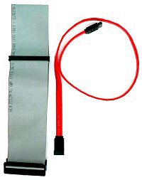 Another
type of drive uses a serial ATA (SATA) cable. This is a newer technology
that uses fewer pins, and fewer wires, but transfers data faster than
100 MBps. A motherboard may have this kind of connector instead of, or
in addition to, PATA (parallel ATA) connectors. In the picture on the right a SATA
cable (the orange one) is shown next to a PATA cable (the
gray one).
Another
type of drive uses a serial ATA (SATA) cable. This is a newer technology
that uses fewer pins, and fewer wires, but transfers data faster than
100 MBps. A motherboard may have this kind of connector instead of, or
in addition to, PATA (parallel ATA) connectors. In the picture on the right a SATA
cable (the orange one) is shown next to a PATA cable (the
gray one).