This chapter discusses hard drives. The objectives important to this chapter are:
Concepts:The chapter begins with a review of floppy drives, removing the need for a separate chapter on them. Floppy drives have some characteristics in common with hard drives, so this discussion is of value to this chapter. The chapter presents two views of how data storage and retrieval take place: a physical view and a logical view. The chart below presents some physical features of different types of floppy disks used at different points in history. Note, these are not the only models that were ever used. They are, however, commonly discussed types. Only the 1.44 MB disk drive is commonly available now.
You don't see many floppy disks in any size except the 3.5 inch, 1.44 MB type. The older ones (5.25 inches) are not practical. The 2.88 MB type didn't sell well, so they are rare. The historical progression for most users was from a 360 KB (5.25 inch) floppy, to a 720 KB (3.5 inch) floppy, to a 1.44 MB (3.5 inch) floppy. In each case, the medium capacity doubled. In the case of the 2.88 MB floppy, there were other alternatives available that were more practical (like 100 MB ZIP disks). Now, we use USB devices, but that is another topic. Floppy drives must be connected to a controller with a data cable, and connected to power with a power cable. The data cable will probably be a 34-pin flat ribbon cable. This cable will have a connector on one end that fits the controller. The other end will have a connector that fits the drive, and there may be another connector in the middle of the cable for a second drive. Note that the primary floppy drive (usually drive A:) connects to the cable's end, while a second drive (B:) would use the connector in the middle. Power is run to the floppy drive by a cable from the power supply. The power connector for a floppy drive, in the past, was typically smaller than the connectors used for other devices (hard drives, CD-ROMs, etc.). Current devices tend to use standard four pin power cables. In order for disks to store data, there has to be a system of organizing the data. Disks are divided into tracks, which are concentric circles. Note that all the disk types listed above, except the 360 KB disks, have 80 tracks per side. Floppy drives read and write to the tracks with magnetic read/write heads (like in a tape recorder or VCR). The heads take turns, writing to one side then the other, so the user does not have to be aware that both sides are used (and does not have to flip the disk over, as I had to with my first computer: an Apple IIc). Floppy drives rotate at about 360 rpm (revolutions per minute), and the read/write heads are meant to make light contact with the disk. This is part of what causes a floppy disk to wear out after about 40 hours of actual use.
(In the picture on the right, the number of wedges has been reduced to make the image clearer. The picture is a metaphor, not an exact representation.) Something that does not vary, at present, is that a sector can only hold 512 bytes of data, no matter what kind of disk is being used. (Okay, one more time. I made it blue so you would know I meant "a segment of a specific track".) Since there are two sides to that disk, that means it can hold 512 bytes per sector, times 2 sides, times 1,440 sectors per side, making 1,440 Kilobytes, which is 1.44 Megabytes. (In this paragraph, every time I used the word "sector", I meant "a segment of a specific track".) The next major concept is the cluster, sometimes also called a file allocation unit. Think of sectors and tracks as being physical aspects of a disk that are dealt with by the BIOS. Think of clusters as being logical aspects of a disk that are dealt with by the Operating System. A cluster is defined as the smallest unit on a disk that the operating system can read from or write to at one time. Again, the chart above is helpful. For the type of disk we are discussing (1.44 MB), the smallest amount of data that can be written to the disk (a cluster) is the size of one sector. For the other types, it varies between one sector and two sectors. Page 252 begins the discussion of formatting disks. Four actions are listed that take place when a disk is formatted:
As you can see, formatting a disk creates or recreates the storage scheme of the disk, which means that it will remove the records of files already stored on it. The chapter continues with a discussion of hard drives. Hard drives (or hard disks) are called that because the actual disks involved are made of metal instead of plastic. The reason they are metal is so they can spin faster for more rapid access to greater amounts of data. Some (but not all) hard drives have multiple disks in them, which are called platters. Each side of a platter could be called a head, as your text explains, but I have never head this term used this way. The term head is more commonly used to refer to the read/write head, which is the part of the drive that reads and writes data to the disk. (Floppy drives and hard drives both have read/write heads.) A hard drive must have one read/write head for each side of each platter in the drive. The heads are mounted on an actuator, which is a mechanical arm that moves across the disk like the arm on a record turntable. (If you have never owned one, and have never seen one, go see a movie! Here is an illustration on Wikipedia.) The platter spin rate varies from model to model, but it is usually in excess of two thousand revolutions per minute (RPMs). The heads actually fly just above (and below) the platters like hovercraft. If a head were to hit a hair or a dust particle at that speed (imagine it on the disk, speeding toward the head...) there would be an actual crash as the head hit the media surface. This is why hard drives are sealed air-tight: to avoid dust, hair, etc. entering the drive. Another new term having to do with hard drives is cylinder. Every platter will have tracks, once it is formatted, and the tracks are numbered, as they are on a floppy disk. Since there can be multiple platters, we refer to all tracks with the same number as a cylinder. For instance, if our drive has three platters, it has six sides, and all six sides have tracks. All six tracks called Track 1 can be considered together as Cylinder 1. For a good lesson on basic hard drive technology, with very nice pictures, follow these links to Marshall Brain's web site, How Stuff Works. Formatting is discussed in the chapter, as it relates to hard drives.
The text discusses some currently common types of hard drives. Most hard drives you encounter will be variations on IDE (Integrated Device Electronics) or EIDE (Enhanced IDE). These include:
Note that the lines highlighted above use an 80 conductor data cable, as opposed to the standard 40 conductor cable. Both of these cables are parallel ATA (PATA) cables. An 80 conductor cable actually has 40 pins, just like the 40 conductor cables used by the types that are not highlighted. The other 40 wires are grounds to reduce crosstalk (signal crossover) from the other data wires. This type of cable may be called 80 conductor IDE cable, ATA/100 cable, or UltraDMA 100/66 cable. 80 conductor cables can be used in place of 40 conductor cables. Do not use a 40 conductor cable in place of an 80 conductor cable, since this will reduce the performance of drives that require the newer cable.
A motherboard may have this kind of connector instead of or in addition to PATA connectors. In the picture on the right a SATA cable (the orange one) is shown next to a PATA cable (the gray one). Most PATA style IDE data cables will allow you to connect two IDE devices to each IDE channel on the motherboard. The text notes that if you place two devices that have different data speeds on the same channel, they may both run at the speed of the slower device. In order for the devices to run at their own rates, the motherboard chip set must support Independent Device Timing. This is a common feature in current chip sets, but not common in older chip sets. Although this chapter is mainly about hard drives, the text notes that IDE devices can also be CD drives, DVD drives, ZIP drives, and other data storage devices. When connecting two devices to one channel, one device is designated the master, the other is designated the slave. The two channels are designated primary and secondary. If your IDE channel connector are different colors, the blue one is probably the primary channel. SATA cables connect to just one device each. Since a motherboard may have two or more SATA connectors and two PATA connectors, you would expect to be able to connect six devices (or more) to them. This is true if you are using Windows 2000 or XP, but if you are running Windows 9x or NT, you are limited to connecting only four IDE devices. (PATA and SATA devices all fall under the IDE standard.) Small Computer System Interface (SCSI) drives are a special case. SCSI is actually a kind of bus, and devices that attach to a SCSI bus can be daisy-chained, providing you have the proper cables, and providing your devices have SCSI input and output ports. A device that only has one port on it can only go on the end of a chain. Since SCSI is a bus, devices that are attached to it must be addressed (numbered). If your SCSI bus will accommodate 8 devices, they are addressed from 0 to 7. If your SCSI bus will accommodate 16 devices, they are addressed from 0 to 15. The actual SCSI card that plugs into your PC gets one of these addresses, and so does each device in the chain. The text covers SCSI in more detail in the appendix on SCSI.
FireWire is a serial port technology that can transfer data at rates up to 400 Mbps. All Apple Macintosh computers now come with FireWire ports and support built in. (Click the logo on the right to jump to Apple's page about FireWire.) The bad news is that most PCs do not have FireWire ports built in, nor do all operating systems support it. Windows 95 and Windows NT do not, but other versions (98, 2000, and XP) do. IEEE standard 1394b provides for a version of Firewire that can transport data at 800 Mbps. The text offers some advice about buying a new hard drive. Several features should be considered:
The text suggests running the setup utility on your computer to find out what kind of drive(s) it has now, to shop for compatible equipment later. A hard drive keeps track of the location of data with a directory listing and a FAT table, just like a floppy disk. A hard drive can have two (redundant copies) of several kinds of FAT tables.
This is a chart of cluster sizes for various logical drive sizes using FAT12, FAT16, FAT32, and NTFS. For another view of the same data, see this page at the Microsoft Help and Support site.
You may wonder why we don't just use NTFS on all large hard drives. It is because NTFS is not available unless you are running Windows NT, 2000, or XP. We can consider a file system to be inefficient if it uses more than 8 sectors for a cluster size. By this measurement, FAT16 is only efficient for hard drives up to 256 MB, and FAT32 is only efficient for hard drives up to 8 GB. The user is cautioned to read all documentation on a new device before installing it, to have a good boot or rescue floppy on hand (test it, or you don't know it is good), and to check the system requirements for the device. It is possible that an older operating system or an older BIOS will not support a new device without an upgrade first. Setting the drive's role is often done by setting a jumper across one pair of a set of pins. Often, no jumper is needed if the drive is your only drive on an IDE channel, but a jumper is applied when you have multiple drives to designate one as the master, and the other as the slave. (NOTE: the pin configuration varies from drive to drive, so check the documentation for the drive you are installing.) General precautions:
IDE controller connections on a motherboard are common. The primary connector may be labeled "Primary" or "IDE1". Look for the marker for pin 1 on your connector cable, on the motherboard, and on the drive. After installing the drive, it may not work. Some possible troubleshooting steps:
If your BIOS supports it, the text recommends using an IDE Autodetection setting. If not, you should set the BIOS values to those recommended by the manufacturer of the hard drive. For hard drives less than 528 MB, use CHS or Normal settings. Larger hard drives need LBA or large mode, so you should make sure your BIOS supports one or both before buying a larger hard drive. If you run into this problem, page 278 suggests five alternatives:
After a drive is installed, you may have to partition it. The FDISK utility in DOS or Windows 9x is used for this. As you may know, FDISK is also used to assign drive letters to the disk. You should be aware that the system will boot from the primary partition, which is why it must be set as active. The primary partition cannot contain more than one drive letter. If more drive letters are desired, they must be assigned in an extended partition. In modern versions of Windows, disk management may be done through Windows Explorer. Right click the disk in question, and select Properties. The Tools tab of the Properties menu will have choices for Error-checking and Defragmentation. Page 294 begins a discussion of troubleshooting common problems encountered while installing hard drives. Some guidelines are given that are good reference material:
When calling the technical support people for any hardware device, you will want to have the information listed below handy. You will note that no one could remember all this minutia, so be at the machine with the problem when you call.
|

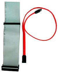 Another
type of drive uses a serial ATA (SATA) cable. This is a newer technology
that uses fewer pins, and fewer wires, but transfers data faster than
100 MBps. The standard may allow transfers as fast as 600 MBps in the future.
Another
type of drive uses a serial ATA (SATA) cable. This is a newer technology
that uses fewer pins, and fewer wires, but transfers data faster than
100 MBps. The standard may allow transfers as fast as 600 MBps in the future.

