|
|
CAP 201a - Computer Animation I
Lesson 7 - Chapter 10, Introduction to Materials
Objectives:
Chapter 10 introduces the materials, maps,
and the Material Editor. Objectives important to this lesson:
- Materials
- Material Editor modes
- Using the Compact mode Material Editor
- Multi-Subobject materials
- Selecting polygons in different ways
- Named selection sets
- Reflection map
- Bump map
- Adding a map to a material
- Mapping types
- Tiling
Concepts:
A material is like a coating that is applied
to objects in a scene. You can think of it like paint or contact paper
that can cover any object you want it to cover.
A material can be a simple graphic image that defines a color, but it
is often much more. A defined material can have several useful
properties (like transparency, texture, and glossiness) which are
discussed in the chapter.
Mapping is the activity of applying materials
to objects, giving them a simulated detail that does not exist in their
actual surface.
Our books often use the word texture without
defining it. We might define it two ways:
- the physical composition, appearance,
and feel of a surface (real world)
- the end result of a material (making a
material seem like the real world)
Most images in games or movies, such as brick walls or pool
balls, can be created with a texture map. Maps
are what we add to a material in 3DS Max to give the material a
specific appearance and simulated feel. There are two categories and
several types of maps. The two categories are bitmaps
and procedural maps. Essentially, bitmaps
are any kind of raster image (these get blurry when
scaled) while procedural maps are vector
images that can be scaled without losing detail. We will see some of
each, working with 3DS Max.
Most materials will have some common characteristics. Three of
them are listed on page 202:
- ambient color - the surface
color of an object when it is exposed to indirect
light
- diffuse color - the surface
color of an object when it is exposed to direct light
- specular color - the color
of reflections (highlights) on an object
 Think about that for a moment. In the example
on the right, the pool ball illustrates all three concepts, and more.
Ignore the black and white parts of the ball for now. Think about that for a moment. In the example
on the right, the pool ball illustrates all three concepts, and more.
Ignore the black and white parts of the ball for now.
- The ambient color of the ball (where the
light is not shining) is a deep
red.
- The diffuse color (where the light is shining,
but the ball is not reflecting a light source)
is a brighter red.
- The specular color, in this case, is the
color of the white spot at about 11 o'clock on the
ball's surface, where the light source in the scene is
actually being reflected by the ball. That white
circle is called the specular highlight. The size of
that area is determined by the material's glossiness
property.
- There is also a falloff area around the
specular highlight. In that area the specular color fades into the
diffuse color.
The text turns to discussing the main tool you will use to
manage materials: the Material Editor. It can be used
to assign and/or create materials for your scenes. As is usual, the
authors give you a menu command to open the Material Editor. Most
people who use 3DS Max would not use this command, however. The hotkey
command to open the Material Editor is the letter M.
If you were going to use a mouse, you would probably click the Material
Editor button on the main toolbar. The advantage to using the
menu command is that it gives you a choice between starting in Compact
view or Slate view. (The same choice is available in the Material
Editor button through its flyout options.)
A common configuration for the Material Editor is shown on
page 203. This is now called the Compact view. If you
learned to use the Material Editor in an older version of 3DS Max, this
is what you learned. The Slate Material Editor in
version 2012 (the current default) will seem strange. It contains
features that older versions simply did not have. If you are in a hurry
to use the Material Editor for a project and need it to look more like
the older versions, use this method to change its appearance:
- Open Material Editor by clicking its button on the 3DS Max
toolbar.
- Open the Modes menu on the Slate Material
Editor screen.
- Select Compact mode.
You can use this method to toggle the view back
to the Slate Material Editor as well, by choosing Slate Material Editor
in step 3.
In the exercises in chapter 10, the text uses the Compact
Material Editor to show you the functions of that mode. This is useful,
because you will not always have access to a newer installation of 3DS
Max, and you should know how the simpler version works.
When a new scene is started, the Material Editor will not have
any materials loaded in its sample slots. The slots all contain what
3DS Max calls a default material. You can load
a material into a slot (for use in the scene) by first clicking
a slot, then clicking the Get Material button,
which is the first button on the left in the Material Editor's horizontal
toolbar. (There is also a vertical toolbar.
You can see both of them in the illustration on page 203.)
Alternatively, if you only wanted to add a color to
the default material in a slot, you could follow the procedure to do so
in the exercises that follow, to set a custom color
based on RGB (Red, Green, Blue) values or HSV
(Hue, Saturation, Value) values.
On page 203, the text describes the functions of most of the
buttons in the Material Editor, but it is unlikely that you will
remember them until you use them. I will describe some of the concepts
from that section here, with the understanding that you will learn the
details about these concepts as you use them:
- library - There is a materials library
that comes with 3DS Max, to which you can add materials that you make,
and materials that you harvest from scenes that you load.
- show map - There is a show map in
viewport button that toggles between showing the texture map
for a material in the viewport, or only showing it when the scene is
rendered. This is not important for materials that do not use maps. You
should be aware of it because you may wonder why you cannot not see a
map that you assign to a material.
- hierarchy - Materials can have channels
(parts) that can be arranged in a parent-child
hierarchy.
- material type - Different material
types have different sets of properties,
allowing them to be configured and used differently
- shader type - Setting a material's shader
type determines how it reacts to and reflects
light in a scene
- map buttons - The diffuse
and specular color swatch buttons
on the Materials Editor have map buttons next to them
that you can click to browse for a texture map to apply to the material.
- specular level - The brightness
of the specular highlight.
- glossiness - The size of
the specular highlight.
- self illumination - A large value here
means that the material does not show shadows well,
and that it does not require lighting because it glows.
- opacity - High opacity
means the material is more opaque, low
opacity means that it is more transparent.
This is the last topic before we begin the project for this
lesson. Shader types affect the way light is
reflected from an object (several types are named for the people who
developed them):
- Anisotropic ("not shaped the same")
- Have you ever seen the moon reflected onn water, so that it stretches
out in only one direction? This one makes asymmetric reflections and
highlights; suggested for brushed metal. Read this
discussion of the effect as seen on water, on multiple reflecting
surfaces, and on grainy surfaces.
- Blinn - the default
shader type; gives a round highlight, good for most materials
- Metal - good for smooth metal material
- Multi-layer - has two
anisotropic parameters, to be set differently; recommended for shiny
materials (like silk) whose layers reflect differently
- Oren-Nayar-Blinn - a softer version of
Blinn, good for cloth and skin
- Phong - supports a shader from older
versions of the program; similar to Blinn, highlights are not as round
- Strauss - simple shader, not clear when to
use it
- Translucent - allows light to pass through
it, can simulate self-illumination
The text provides a description of the real Red Rocket toy's
wheels on page 205. Note the words used on this page and the next to
describe the wheels: white, smooth,
shiny, reflective. Compare
these to the words describing the tires: black,
still shiny, rough, distorted by bumpiness,
slightly matte. The hubs of
the wheels have yet another texture and look: red, shiny,
plastic. These are descriptions that should be
handled by mapping a different material to each part of the wheels.
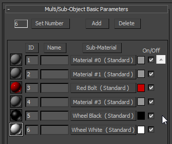
Each wheel is only one object however, so the text recommends using Multi/Sub-Object
materials.
Project Exercise 1: Creating a
Multi/Sub-Object Material
This exercise starts on page 205. It returns
to the Compact Material Editor. Set your project folder to be the Red
Rocket folder, and open the supplied file named in the text.
- Open the Compact Material Editor. Choose the first
sample slot. Name the material. (This can be done
before you edit a material or after you have done so.)
The book does not mention how to
name the slot. If you have picked the first one (and why wouldn't you?)
there is a box in the editor that says "01 - Default".
Click in that box, remove that text, and type Red Bolt, as the book
says. Press the enter key and the material is named.
 Be aware
that the Material Editor works like the command panels: the parameters
area of the editor scrolls to show lots of rollouts,
and what appears in that part of the screen will vary
based on what you just clicked. Be aware
that the Material Editor works like the command panels: the parameters
area of the editor scrolls to show lots of rollouts,
and what appears in that part of the screen will vary
based on what you just clicked.
Scroll (or drag the panel vertically) if you do not immediately see the
Blinn Basic Parameters rollout. You would
not even see it, by the way, if the Shader parameter
were set to anything other than Blinn.
Click the gray box next to the word Diffuse that my mouse pointer is
over in the image for this step. That box is the Diffuse Color Swatch.
Set the value for the Diffuse color
for this material as instructed. Note that the Color Selector
has spinner buttons. If you want to change the value for a field that
has a spinner button to zero, you
can just right-click it. (It will automatically go to
the lowest possible value, which is 0 for color values.) Click OK
on the Color Selector window when you are done.- Watch the color sample change as you
modify the values for Specular Level (higher is
shinier) and Glossiness (higher is a smaller
highlight).
- Select the next sample slot, name it, and
set its Diffuse color. Note that the text does not
tell you what values to use for white. Pure white is
attained by setting the red, green,
and blue spinners each to 255. You
may want to vary this a bit, to get a more realistic
tone. Set the Specular Level and the Glossiness
the same as the previous slot.
- Select the next sample slot, name it, and
set the Diffuse color to black.
Again, you may want to use a variant of black, instead of setting all
color components to 0. Note that you are told to set
the Specular Level to 50 and the Glossiness to 20.
Question 1: What are the
general effects of setting the Specular Level to 50 instead of 90, and
of setting the Glossiness to 20 instead of 80?
- Save the file with a new
name, preferably one with your initials and a version
number in it.
The text starts a new exercise. In it someone has made a terrible
error: the picture in the text for step 3 has nothing to do
with the instruction, which itself is uninstructive. Let's fix that.
Project Exercise 2: Selecting polygons
and named selection sets
This exercise starts on page 207. It has
problems, so read it, then come back here for
corrections.
- Continue in the file from the last exercise. Press F4
to see edges (unless they are already displayed), and press F2
to see selected polygons lit by their edges only.
- You should only see a wheel and a large part of the rocket
model. Select the wheel as instructed. Don't
bother going to Polygon subobject mode.
- This is the step where they tell you to select all the
polygons in the tire portion. They specify no method, so you are left
to obit the scene while trying to click every hidden polygon that you
want. That's a silly way to do it. Do this instead:
- Change to edge selection mode.
Isolate the wheel if you like, but it won't be necessary this time.
- You can Orbit the scene to get a view
like the one shown in the three images below.
- Click outside the wheel to deselect
any edges already selected. This is a useful habit when making a new
selection: make sure you select only what you want to select.
- Click one of the edges that goes
across the tread of the wheel. (See the red line in the first image
below.)
- On the Graphite ribbon, Modify
Selection tab, find and click the Ring
button. The same edge in all positions around the wheel will be
selected. (As shown in the second image below.)
- Click the Ring Grow button on the
Graphite panel (it is the one with a plus sign just below the Ring
button) and guess what? Nothing happens!
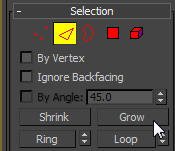 Instead, find the Grow
button on the Modify panel, and click it three
times. The selection set will grow toward the axle, in each direction,
with each click. (The result is shown in the third image below.) Instead, find the Grow
button on the Modify panel, and click it three
times. The selection set will grow toward the axle, in each direction,
with each click. (The result is shown in the third image below.)
| d. Click an edge |
e. Click Ring |
f. Click Grow 3 times |
 |
 |
 |
- Hold down a Ctrl key and click the icon
for Polygon subobjects. (It has to be the icon,
not the word in the modifier stack.) The icons on the Modify panel and
on the Graphite ribbon both work. This will select the polygons defined
by the currently selected edges.
- Another good habit: save the selection set
by clicking in the drop down box
that says Create Selection Set, typing
a name, and pressing Enter. Why? Because you don't
want to lose that selection set right now, and if you save it when you
save the file, you can reselect all of those polygons in a second if
you need them again.
- Return to the exercise in this step.
If it is not open, open the Material Editor, in Compact
mode. Drag from the Wheel Black slot and drop
on any of the selected polygons. The material will be
applied. (You can drag and drop the material, but for a
selection set it may sometimes be better to click the Assign Material
to Selection button.)
- Stay in polygon mode, and try to area
select the polygons for the white wheel
cover. It will not hurt if you select the actual hub as well, since you
color it next. Drag and drop the
white material on the selection.
- Try using the edge-ring-polygon method
from step 3 above, as well as the area selection
method to put the red material on the actual hub
of the wheel.
- Save incrementally and show
me your work.
As the book proceeds to explain, you have now loaded an MSO
material in the Material Editor by virtue of using three materials with
one object. The three steps on page 208 confirm this.
Project Exercise 3: Loading the MSO
Material
This exercise starts on page 207. Continue
working with the file you saved at the end of the exercise above.
 Open the Material Editor
and select the next unused sample slot. Open the Material Editor
and select the next unused sample slot.- Find and click the eyedropper
button next to the material name field. Click anywhere on the wheel as
instructed.
- You should see a Multi/Sub-Object Basic Parameters
rollout, but it may have more materials in it than
you applied to the wheel. Mine has the three named
materials, as well as three randomly numbered
materials, indicating that there are at least three parts of the wheel
that I have not applied a named material to at this time.
Name the MSO material as instructed and save
the file again.
Project Exercise 4: Fine-tuning the
materials
The text continues with some modifications to the materials,
using more resources from the student disk. After some discussion, the
exercise begins on page 208. In the course of the
discussion, the authors refer to part of the model being hidden on
separate layers. They are thinking of an older version of this
exercise. There are no parts hidden in this scene. There is only one
layer presently. (We can talk about layers in lab this week.)
Continue with the file you saved in the previous exercise.
- Open the Material Editor. The text says
to select the Red Bolt material.
- Open the Maps rollout and find the
line for Reflection.
- Click the Map button for Reflection
that currently says None. (Yes, it's wide, but it's a
button.)
- Click Bitmap in the list that
appears, and click OK.
- Navigate to the Images folder for
this project, and find the Rocket_Refmap_Blur.jpg
file. Select it and click Open.
- Do a Quick Render of the Perspective viewport.
Back to the lesson. The author has added a material that fakes
a reflection of a scene in the surface of the bolt. You will see in the
render window that the material is too reflective.
- Go back to the Maps rollout by clicking the Go to
Parent button in the Material Editor's horizontal toolbar.
Change the Reflection Amount value to 30. Render
again to see the difference. This may not be the ideal value on your
screen. Experiment, and find a value you like best.
Question 2: What value
looks best to you for Reflection Amount?
- Save incrementally.
Project Exercise 5: Applying a bump map
The text mentioned that the surface of the tire portion of the
wheel should look rougher than the white and red portions. Adding a
bump map will do that. This exercise begins on page 211.
- Continue with the scene file from the previous exercise.
Open the Material Editor and select the black
material. Open the Maps rollout.
- Find the Bump line, and click the Map
button for it. (It should say None at this
time.) This time, click Noise, then click OK.
- On the Parameters screen that appears, find the Size
field and change the value to 0.02. After you have
made this setting, click the Go to Parent button.
- Change the Bump Amount value to 60.
- Render the viewport again, and enjoy your work.
- Save incrementally and show me a
render of the scene.
Project Exercise 6: Fin base material
We will move ahead to page 211 in the text.
The author brings up the point that a map image will not always fit the
object you want it to fit. There is inadequate explanation of what you
are doing in this chapter. For a more informative discussion of the
subject, follow this link
to a tutorial on the UVW Unwrap modifier. For those who don't want to
follow the link, I will do what I can here.
Maps are colors, patterns, or other coverings
that we put on the surfaces of objects. In this lesson, we will look
briefly at tools to use the UVW coordinate system on
maps.
In general, U, V, and W are just the three
letters that come before X, Y, and Z in the English
alphabet (and others). So what? Well, the letters correspond to an artificial
coordinate set. If X, Y, and Z are the Cartesian coordinates
of a 3D object, U, V, and W are the coordinates we would use to measure
the surface of that object if we peeled the surface
off and laid it out flat, like skinning an animal to make leather. As
you might imagine, a flattened pattern for a complex object will have a
very unusual appearance. As such, we will use some special tools in 3DS
Max to manipulate maps for 3D objects.
3DS Max uses the UVW Map modifier to apply
maps to objects more precisely. There are several map types
that apply to classic object shapes:
- planar - for flat surfaces
- cylindrical - for cylinders, with or
without flat ends. If the cylinder has flat ends, we can use the Cap
option to apply a planar map to the ends.
- spherical - meant for spheres (ball-shaped
objects). This one has a limitation we can overcome: the edges
of a map will form a seam on one side
of the sphere, and at the poles (points where the top
edge meets itself, and where the bottom edge meets itself)
- box - a classic six-sided figure, that may
or may not be a cube
This exercise begins on page 212.
- Open the file specified in this step. Save
it with your name incorporated in the filename.
Select the fin on top of the model,
right-click it, and choose Isolate Selection.
- Open the Material Editor. Select a sample
slot, and set the Diffuse color for this slot to
whatever shade of white you used for the wheels.
- Name the material as instructed. Drag
and drop the material from the sample slot onto the fin.
- Set the Specular Level and the Glossiness
for the material as instructed. Watch the fin change as you change each
setting. (The material may look gray in a render window at
this point, due to the lighting in the scene. Lighting comes up in
another chapter.)
- Follow the instructions to add the same reflection
map that you added to the wheels.
- Change the Reflection Amount to 35.
- Do a Quick Render to view the work so
far. Modify the Reflection Amount, if you want to,
then save incrementally. Continue to the next
exercise.
Project Exercise 7: Adding the decal
This exercise begins on page 213.
- If it is closed, open the Material Editor.
Select the Fin_Decal Material.
- Go to the Maps rollout, and click the map
button for Diffuse Color. Click Bitmap,
and OK. Navigate to the file
specified in the text. (It does not match figure 7.79.) Select
it and click Open.
- The map will not appear in a viewport
until you click the Show Shaded Material in Viewport
button. Do so, and note that it looks a lot like figure 10.13. Not very
good, yet.
- Step 4 seems unnecessary. We can already see the material
in the viewport.
The text does not really begin a new exercise, but it starts a
new set of steps at the top of page 214 to add a
modifier.
- Close the Material Editor. In any
viewport, select the fin, the open the Modifier
List, and add a UVW Map modifier to it.
- Verify that you see the orange frame
around the fin.
- Find the Alignment section of the modifier's parameters,
and click the Bitmap Fit button.
- Navigate to the decal file again, select
it, and click Open. The orange frame of the UVW Map
gizmo should change shape to match the proportions of the tiff file.
Again, the text starts a new set of steps at the bottom of
page 214. And they will do it again. This time the steps address adjusting the gizmo.
- Follow the directions in the text to open
the UVW Map modifier in the stack, and to select its Gizmo
element.
- You should see a gizmo in the viewports
that starts out based on the Move tool gizmo.
- Select the Rotate tool on the toolbar.
Read the instruction in the step but wait a minute. It says to rotate
the gizmo on the X axis. I have puzzled over what the authors mean for
a minute and I can say it more clearly.
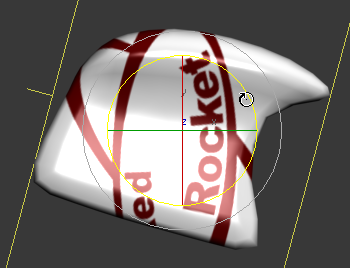 Look at the model in the Left
viewport. Look at the model in the Left
viewport.
Turn on angle lock.
Grab the rotate handle for the Z axis. (It should be
blue, but it may be yellow even before you grab it.)
Watch the transform value for Z at the bottom of the
screen. It says 90 when I grab the handle, but it
changes immediately to 0 when I begin rotating
the decal clockwise, then the numbers become negative
and start to grow.
Drag the handle until the transform value reads -75.
So, what were they talking about? We rotated the
decal with the Z axis tool, which means it rotated using the Z axis as
a center point. It is also true that it rotated through the X axis, but
so what? It rotated through the Y axis as well. Another point of
clarity: when you tell someone to rotate something, tell them which
handle of the tool to use. That represents the axis it is rotating on.
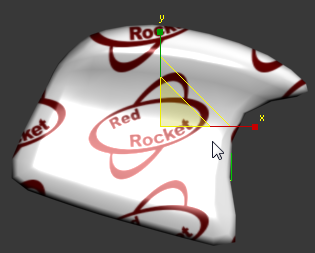 Switch to the scale
tool. Turn off the angle lock and turn on
the percent lock. Drag down
uniformly, and watch the transform values again. Stop when all
transforms are down to 40. You will still see lots of
emblems on the fin, but one will be centered and properly oriented. Switch to the scale
tool. Turn off the angle lock and turn on
the percent lock. Drag down
uniformly, and watch the transform values again. Stop when all
transforms are down to 40. You will still see lots of
emblems on the fin, but one will be centered and properly oriented.
Correcting the projection
- The text informs you that the decal looks fine on the left
side of the fin, but the letters (and the image) appear reversed
on the right side. Look in the Parameters rollout of
the UVW Map modifier.
(The text refers several times to the modifier as the UVW Mapping
modifier. This is the name that used to appear in the modifier stack
once it was loaded. This name no longer appears in the stack. They have
not updated all the references in their old exercise.)
Find the Mapping radio buttons, and change the
mapping type from Planar to Box. (Planar might have
worked well if this were a flag.)
- This takes us back to having the decal show on six
faces of the fin. The fin is no longer meant to have six
sides, so the author has a trick to make it work out.
- In the Mapping section of the Parameters
rollout, find the Height parameter, and change its value
to 0.01. (It is not allowed to be 0, so you make it a small
value.)
- The value used makes the unwanted sides
of the box very thin, so they won't be noticed.
The authors seem to have left out something
important. Back on page 214, they told you a little about tiling, but
they never mentioned that you should turn it off for this material.
Follow these steps to finish the tutorial.
- Open the Material Editor.
- Select the material for the fin.
- If you see the Maps
rollout, click the Map button for Diffuse color,
which will take you to the properties for that map.
If you are already on the properties screen that
includes the rollout shown below, stay on it.

.
- In the Coordinates rollout, shown above,
note that there are two check marks to tile the map
on the U and V axes. (U and V are
like X and Y, remember?)
Turn off the check marks.
- Nothing may seem to happen. Render the
current view again. The decal should no longer tile in the render
window.
- You can also modify the position of the
decal on this rollout with the offset values. Do
this, then render again and be horrified that the
decal now appears in places it should not again.
- Changing the tiling removed the Box
mapping corrections. Repeat those corrections, and check
the model in rendered views again. It should be the best version so far.
- Save incrementally, and show
me your work.
|