|
|
NET 211 - Wireless Networking
Chapter 4, Antennas
Objectives:
This lesson presents background on radio waves, signal
modulation, and the use of radio as a data communication medium.
Objectives important to this lesson:
- Concepts about antennas
- Types of antennas
- Coverage patterns
- MIMO (multiple-input multiple-output)
- Antenna measurements
Concepts:
Chapter 4
The chapter begins with some electrical basics that become
immediately important.
- a conductor is a material that readily allows
electricity to flow through it; most metals are good conductors
- alternating current will produce an electromagnetic
field around a conductor that it passes through
- the electromagnetic field produced by alternating current
will vary as the current varies, producing a field that represents
the variations in the current
- a field produced in this way will radiate away from
the conductor
- if another conductor can receive the radiated
field, a current will be induced in that second
conductor that will match the original current
This is the basis for using antennas to send and
receive wireless signals. Our transmitter sends a current to an
antenna, which radiates a field (signal), which is then received by
another antenna, which is interpreted by a receiver that is
sensitive to the frequencies that were transmitted.
The text tells us that the simplest antenna is just a bare
wire. This implies something important that the text does not
mention: the wire will work best when it is not covered with
electromagnetic insulation, such as the braid sheath in a coaxial
cable. Back to the bare wire, the text calls this form a whip
antenna, which works well when it is about as long as one quarter
of the wavelength being transmitted. (A full wavelength would be
better, but we will come back to that.) The text gives us two formulas
for calculating the proper length of a whip antenna in inches and in
centimeters:
- 2952/frequency in MHz = one quarter
wavelength in inches
- 7500/frequency in MHz = one quarter
wavelength in centimeters
The text also mentions that a proper antenna of this type also needs
a ground
plane. In the illustration on page 122, we see a flat disk at
the bottom of the antenna's vertical element (its radiator) that
is mounted 90 degrees away from the angle of the radiator. That means
they form a right angle. In the illustration I have linked to, we see
a square plane. We are also told on that web page that the ground plane
can be the Earth itself, a car roof, or many other large surfaces that
can reflect waves that the antenna sends toward it, which gives the antenna
the effect of producing additional waves, as we discussed in the last
chapter. This is a positive propagation behavior effect. By the
way, a ground plane does not have to be electrically grounded,
but they often are.
The text gives a few terms that it will use in the rest of the
chapter:
- Intentional Radiator (IR) - any system whose purpose
is to radiate electromagnetic waves; in a confusing footnote, the text
also tells us that the FCC says that IR also stands for the power
that such a system will send to an antenna, not the signal from the
antenna, or the antenna itself; FCC regulations limit power levels of
this sort
- Unintentional Radiator (UR) - any system that
produces electromagnetic radiation, but whose purpose is to not
to radiate electromagnetic waves; an electrical generator would be an
example: it produces ER, but its purpose is to produce electrical power
- Isotropic Radiator - a radiator that sends out
electromagnetic waves in all directions at the same
power levels; this is a theoretical concept: no antenna does this
perfectly
- Equivalent (Effective) Isotropically Radiated Power (EIRP)
- the FCC uses this term to mean the power that is radiated from an
antenna in whichever direction that power is the greatest; this
includes any power amplification added to the signal
- Transmission Speed - I am including this term
because the author continues to use it. It bothers me, but I understand
what he means. The speed of light does not vary within a given medium
(at least, not
yet), but the number of bits per second that we can pass along
a channel varies from one method to another (see the chart
below), so that is what the author actually means. I would prefer to
use the term throughput, but that seems to offend some grammarians.
(Perhaps we should not have asked Grammaria to be part of the Federation.)
| Data Rate (Throughput) |
IEEE 802.11a |
IEEE 802.11g |
| 24 Mbps |
40 mW (16 dBm) |
50 mW (17 dBm) |
| 36 Mbps |
25.1 mW (14 dBm) |
40 mW (16 dBm) |
| 48 Mbps |
20 mW (13 dBm) |
31.6 mW (15 dBm) |
| 54 Mbps |
20 mW (13 dBm) |
20 mW (13 dBm) |
- Decibels Isotropic (dBi) - The text begins
with with the example of an isotropic radiator (which does not really
exist), and explains that we often need to send a signal in a particular
direction instead of sending it in all directions. We cannot simply amplify
the power (also called gain), since that would still go
in all directions. So the text tells us that an active gain (increasing
power to the antenna) is not effective in this case. The solution
uses a passive gain: the same power is used, but it is
distributed differently by using a shaped antenna, referred to in the
text as a high
gain antenna. Examples would be dish antennas and multiple
element TV antennas.
Decibels isotropic is the measure of the passive gain of a high gain
antenna compared to that of an isotropic antenna under the same
conditions. The high gain antenna will send a signal farther
than the isotropic antenna, so the signal strength of the high gain
antenna is compared to the signal strength of isotropic antenna at a
distance they can both reach.
- Decibels Dipole (dBd) - First, we need to
understand that a dipole antenna is often
shaped like the letter T. They don't have to have this shape, but it
illustrates their main characteristic. Power is applied to the base, it
flows to the junction of the vertical and horizontal parts, where the
signal is strongest, and then fades out to end of each of the
horizontal parts. The image
below from Wikipedia shows a signal being sent into a dipole
antenna that is half as wide as the wavelength of the frequency being
used.
The text tells us on page 126 that the the standard value of a dipole
antenna is 2.14 dBi. It is not clear what we are to do with that, so
use this formula to convert between the two measures:
dBi = dBd + 2.14
dBd = dBi - 2.14
Having already introduced us to three types of antennas,
the text tells us about three general classes:
- omnidirectional antennas
- This is the simplest kind of the three antenna types discussed in
this part of the chapter, but the text has discusses three factors
about them.
- horizontal or vertical coverage - The text tries
to tell us that antennas are typically deployed as vertical rods, and the signals from
them tend to radiate as horizontal waves, 90 degrees away
from the orientation of their antennas. The waves do radiate vertically as well, but
to a lesser extent. This is important to know when planning the
deployment of an antenna. If it is supposed to service devices on
floors above and below it, the antenna should be deployed horizontally
to produce the best results for its vertically deployed users. In
practice, it is better to have WAPs on each floor of a building, rather
than have them try to cover multiple floors.
- polarization - As
noted above, the radiating element
of an antenna is at right angles
to the most effective part of
the waves it radiates. Waves follow a plane
that is at right angles to the radiator. That plane is the plane of polarization.
In the illustration above, we can say that the magnetic field of the illustrated
wave is polarized vertically,
and the electric field of the
wave is polarized horizontally.
When we talk about electromagnetic waves in general we do not separate
the two components, and we say that the wave is either polarized
vertically or horizontally, at 90 degrees from the orientation of the
radiator. In general, we would like the orientation of the receiving
equipment to match that of the transmitting equipment.
- antenna diversity
- The text explains that many wireless
access points have two antennas
so that they can receive each signal more than once, even in conditions
in which there is no secondary copy of the signal due to propagation
behaviors. In most cases, the signal received by one antenna or the
other will be stronger than
the other, allowing the WAP to select
and use that stronger signal.
This selection process is called switching,
which is unfortunate, since that word already has a meaning in
networking.
Antenna diversity works in the reverse
direction as well: if one antenna has been selected as better to
receive signals from a given device, the WAP can choose to use that
antenna to transmit to that device.
Some access points have multiple antennas that they use for different
frequencies. See the discussion of MIMO below.
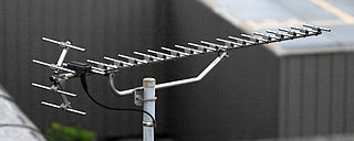
- semidirectional antennas
- Instead of transmitting in a full circcular pattern, a semidirectional
antenna will transmit across a half circle (a semicircle) or less. The
design and construction of the antenna will determine what angle its
transmitted waves will cover. The illustration below is a Yagi antenna
for TV reception. Its design makes it more effective for receiving
signals from a particular direction. In this case, from a transmitter
to the east northeast, assuming we are looking north in the photo.
- highly-directional antennas
- This kind of antenna will transmit across the greatest distance, all
other factors being equal. They are often dish antennas, as noted above,
and they require more care to focus them on their intended source or
target. Each of these types of antennas is illustrated and discussed
on this
web page.
The text changes topics to discuss coverage patterns for antennas.
- azimuth and elevation
- This section actually covers some other facts first:
- antenna radiation chart
- This is a polar graph, showing how an antenna radiates its signal.
This kind of graph is circular, as shown on pages 132 and 133. Each
location on the graph can be described by its distance from the center,
and by the number of degrees it is away from the 0 degree line.
- Antenna location -
The antenna is located at the center of an antenna radiation chart.
- degrees - This
chart divides a circle into 360 degrees, which is the most common way
of looking at a circle.
- circles in the graph
- It is common to show circles in the graph that correspond to distances
at which the signal strength drops significantly. In the examples in
the text, we should read that the signal strength has fallen to 0 at
the outermost circle, and the numbers on the inner circles are the signal strength remaining (in dB) at those locations. In the link
I have supplied, another author show us a different way to look at
similar data. He is showing us the percentage
of signal remaining at each distance in an asymmetric pattern.
- Azimuth chart -
The chart on the left on page 133 is an azimuth chart, as is the second
chart on the web page at the link above. An azimuth chart shows the
signal pattern when viewed from above.
This is the most useful chart for showing the most effective locations
for receiving signals from this antenna, in terms of horizontal distance from the antenna.
- elevation chart
- The chart on the right on page 133 is an elevation chart, which shows the
signal strength from an antenna when viewed from one side. This kind of chart shows
the strength of a signal in terms of vertical
and horizontal distances from
the antenna. In the example in the text, the two charts are meant to
represent the coverage shown by the 3D graphic above them. It is
tempting to rotate this chart in your mind to envision the 3D graphic,
but that would not be correct in the case of an signal pattern that is
not symmetrical. In that case, several elevation charts might be more
informative.
- beamwidth - This is
a measure of an effective part of the radiation pattern of an antenna.
It assumes that there is a most powerful
direction of radiation, so this applies more to any sort of directional antenna. From the most
powerful part of the signal being sent, the signal is measured to each
side to find the places where there is a reduction of -3dB, which is a
50% reduction in signal. These points mark the useful beamwidth for the
signal. As the text states, this measurement can be taken on an azimuth
or elevation chart.
- Fresnel zone - The
text first discusses line of sight, which is a related concept. A
visual line of sight means that you can see something. An RF line of
sight means you can receive a signal from something, which is different
because of signal diffraction, scattering, etc. Surrounding an RF line
of sight are several theoretical Fresnel zones. Imagine them as a
series of long balloons. The first zone encloses the line of
sight. The second zone
encloses the first zone, and so on. Signals passing through a Fresnel
zone will be out of phase with
the original signal. Signals passing through each higher numbered zone are more out of phase with the original
signal than those in the next lower numbered zone. The text discusses
obstructions in the various zones, but the bottom line is that we are
better off if the RF line of sight to the target is clear. The text
offers a list of suggestions for improving reception, but they all come
down to raising the transmitter and receiver above whatever is in the
way, or clearing away the obstruction.
The next topic in the chapter is MIMO (multiple-input
multiple-output). The text gives us a little background on the
general subject first.
- IEEE 802.11a, b, and g specifications all say that a device
can only receive or transmit on one antenna at a time. This is why a
device using one of those protocols that has antenna diversity must choose
an antenna to use when it receives on both of its antennas.
- A system that performs as described above is a single-input
single-output (SISO) system. (I am going to bet they did not
need that acronym until the development below.)
- IEEE 802.11n uses a multiple-input multiple-output (MIMO)
system. A MIMO system has a separate processor and radio for each of
its antennas, as shown in the diagram on page 137.
- Each separate combination of a processor, a radio, and an
antenna is called a radio chain, whether the system uses SISO
or MIMO.
The text lists several technologies that can be used in MIMO:
- Spatial Diversity - The main point is to use
multiple antennas to send and to receive signals. The first benefit is
that sending multiple copies of one signal from multiple
antennas means each of those copies will be likely to take a
different path to the receiver, and will undergo different amounts
or different types of damage, increasing the odds that one will
be better than the rest.
The second benefit is that sending out multiple copies at once makes it
more likely that the signals can be interpreted together, and
that a larger portion of it will be understandable.
- Spatial Multiplexing - This technique sends different
data streams through multiple radio chains at the same
time, which increases throughput when they all can be received and
reassembled correctly. The text gives us a notation used to understand
how spatial multiplexing is implemented on a given device.
Example 2x3:2 would mean that the device can use up to 2 antennas to transmit, and it can use up to 3 antennas to receive, and can handle up to 2 data streams at once. I have added the colors
for reference.
- Maximal Ratio Combining (MRC) - Most mobile
devices only have one antenna. When a signal from such a device is
received by a MIMO device, the MIMO device still receives multiple
signals due to propagation behaviors. The MIMO device adjusts the
various signals for phase and amplitude, and combines them into the
best possible copy. The method used to do so is called Maximal Ratio
Combining.
- Transmit Beam Forming (TxBF) - The short form
of this item is that a transmitter can change the beamwidth or the
direction of signals to avoid signal interference. TxBF is the method
it can use to do so.
The text discusses several topics dealing with antenna
installation. The section begins with the observation that 802.11n
antennas are all internal, which makes the spacing of those antennas
follow a rule that says they need to be more than half a wavelength
apart. So how far is that? The text tells us that the wavelength for
2.4 GHz is 12.5 cm (4.9 inches) and the wavelength for 5 GHz is 6 cm
(2.3 inches). Nice to know.
- A wireless access point is commonly located as close to
the middle of its intended coverage area as possible. This is
sometimes mitigated by the practice of mounting it high on a
wall or on the ceiling to avoid obstructions and to prevent
easy theft.
- The text recommends that we should never place any
electrical equipment, including access points, in plenum space. The
possibility of fire in a plenum is unacceptable.
- Some systems will need an amplifier
added to bring the signal up
to the power level the FCC allows. Amplifiers come in two types for these systems: unidirectional amplifiers boost
power at the antenna, and bidirectional amplifiers boost power
either at the antenna or at the device that connects to the
antenna.
- Some systems will need an attenuator
added to bring the signal down
to the power level the FCC allows. Attenuators
can be fixed-loss or variable-loss, but only fixed-loss attenuators are allowed
on WLANs by FCC rules.
- Use connecting cables that
are short whenever possible,
and make sure they can handle
the power levels on your system.
- Use as few RF splitters
as possible. They are not allowed on 802.11n systems.
- The text recommends installing lightning arrestors, but warns that
they do not protect equipment
from direct lightning strikes.
A lightning arrestor only protects equipment from the surge of RF energy that would be
caused by a nearby lightning strike.
The last topic is about more antenna measurements.
- link budget - The
text tells us that this term refers to the sum of the gains and losses
in power between a transmitter and a receiver. We are give a list of
factors in this concept, but we are not given an equation to use. This discussion on Wikipedia shows that it is as the text implies, a simple addition and subtraction problem.
- antenna gain
- free space path loss
- frequency
- loss at each connector
- number of connectors
- path length
- power of the transmitter
- length of cable used, and loss per unit length of cable
- System Operating Margin (SOM) - also called the fade margin,
this is the difference between the level at which a signal is received,
and the level at which it can be used/decoded/understood; this can be a
positive number (if we can use the signal) or a negative number (if we cannot use the signal)
- Voltage Standing Wave Ratio (VSWR) - This measure compares
the voltage that we put into a system to the voltage that comes out of
it, typically at the antenna. It is expressed as a ratio, and the ideal
ratio would be 1:1. Higher ratios like 2:1, 4:1, or 10:1 show a
mismatch in the components of a system, and may result in reflected
signals or burn out of components.
|